
NATIONAL TECHNICAL REGULATION ON SAFETY AND ENVIRONMENTAL PROTECTION FOR URBAN BUS
Preface
The QCVN 10:2015/BGTVT is compiled by the Vietnam Register, appraised by Ministry of Science and Technology, and promulgated by Ministry of Transport under Circular No. 90/2015/TT-BGTVT dated December 31, 2015.
The QCVN 10:2015/BGTVT replaces QCVN 10:2011/BGTVT.
NATIONAL TECHNICAL REGULATION ON SAFETY AND ENVIRONMENTAL PROTECTION FOR URBAN BUS
1. GENERAL PROVISIONS
1.1. Scope
This Regulation prescribes technical requirements and technical quality, safety, and environmental protection inspection for urban buses of at least 17 seats (hereinafter referred to as “vehicles”).
1.2. Regulated entities
This Regulation applies to facilities manufacturing, assembling, organizations, individuals importing vehicles, vehicle parts, and agencies, organizations, individuals related to management, examination, testing, and certification for technical quality, safety and environmental protection of urban buses of at least 17 seats.
1.3. Definitions
This Regulation uses terms defined under the QCVN 09:2015/BGTVT “National technical regulation on safety and environmental protection for automobiles” (hereinafter referred to as “QCVN 09:2015/BGTVT”) and the following terms:
1.3.1. “urban bus” means a passenger automobile designed and equipped for use in the city and suburban areas; this type of automobile contains seats and standing areas for passengers; allows passengers to move in a manner that suits regular stopping and parking of the vehicle.
1.3.2. “articulated bus” means an urban bus consisting of at least 2 rigid cars connected by a rotating joints and allowing passengers to move from one car to another. The coupling or decoupling of cars can only be carried out at factories.
1.3.3. “double-deck bus” means an urban bus consisting of 2 decks both of which can facilitate passengers while the top deck does not facilitate standing areas.
1.3.4. “urban bus without roof”(*) means an urban bus without roof covering a part or the entire floor of the vehicle. In case of a double-deck bus, only the upper deck is allowed to have no roof. If floor of a vehicle is either partially or entirely not covered by roof, standing areas for passengers must not be provided on that floor section (hereinafter referred to as “open top vehicle”).
1.3.5. “intercommunication staircase” means the staircase connecting the first deck and the second deck of a double-deck bus (hereinafter referred to as “stair”).
Note: (*) The sale and circulation of this type of vehicle shall be elaborated by competent authority.
1.3.6. “half-staircase” means a type of staircase connecting the second deck to an emergency exit of a double-deck bus, is referred to below as exit staircase.
1.3.7. “contrast” means the level of contrast of light reflected off surfaces of parts and equipment of the vehicle due to their difference in colors.
1.3.8. “optical device” means a variety of equipment (including mirrors, monitors forming a closed network, etc.) which helps operator to observe different sections of the vehicle.
1.3.9. “seat” means passenger seats, not including seats of operators and attendants.
1.3.10. “deep of tread” refers to horizontal distance from the outer edge of a tread to the riser of the next tread above or to the vehicle floor.
1.3.11. “doorway area” means an area within a 1 meter horizontal radius from the door;
1.3.12. “external step” means the first step out of or into the doors from the near side.
1.3.13. “floor” means a part of the vehicle body whose upper surface supports standing passengers, feet of sitting passengers, operators, attendants, and seat frames;
1.3.14. “access passage” means the passage that travels through the doors to gangway.
1.3.15. “double or multiple window” means an emergency exit window divided into two or multiple sections by one or many vertical lines (or vertical planes) where each section has dimensions and access thereto appropriate to regulations applicable to a regular emergency exit window.
1.3.16. “driver’s compartment” means a space dedicated specifically for driver except for cases of emergency, contains driver’s seat, steering wheel, mechanism, switches, control devices, and other equipment serving the operation and control of activities of vehicles.
1.3.17. “passenger's compartment” means a space occupied by passengers. Toilets, kitchens, liquor bar (if any) are not considered passenger’s compartment.
1.3.18. “total floor area” serving as the basis for calculating, determining minimum priority floor area, means the entire floor area of the vehicle, or in case of a double-deck bus, total floor area of the first deck bar the driver’s compartment, fender, access compartment, staircases, or all voids intended for luggage.
2. REGULATION ON SAFETY AND ENVIRONMENTAL PROTECTION
Urban buses must meet requirements under QCVN 09:2015/BGTVT and this Regulation. In addition, urban buses accessible for persons with disabilities must meet technical requirements pertaining to accessibility under QCVN 82:2014/BGTVT.
2.1. Technical parameters
2.1.1. Percentage of load distributed on steering axle (or steering axles) must not be lower than 20% of the vehicle's load when the vehicle is not loaded and 25% of the vehicle’s load when the vehicle is fully loaded. In case of articulated buses, this percentage shall be calculated in the first car and must not be lower than 20% when the vehicle is not loaded and fully loaded.
2.1.2. Turning radius: Specified under Appendix hereof.
2.1.3. Maximum slope degree which the vehicle can traverse must not be less than 20% when the vehicle is fully loaded and 12% when the vehicle is an articulated bus.
2.1.4. Cargo or luggage spaces are not allowed on top of the vehicle.
2.1.5. Floor area for passenger S0 means total floor area of the vehicle minus:
- Driver’s compartment area;
- Area of external steps and any locations with steps where the deep is less than 300 mm;
- Sweeping area of doors and mechanical parts thereof during opening and closing of the doors;
- Area of coupling section (in case of articulated bus) must prevent passenger access according to 2.5.9.6;
- Area of staircase, exit staircase, and treads;
- Area of kitchen, liquor bar, and toilet (if any).
2.1.6. Floor area for standing passengers S1 is calculated by floor area for passengers S0 minus:
- Floor area with a slope greater than 8%;
- Floor area that is not accessible by standing passengers when all seats have been occupied;
- Area of sections where height from the floor is less than the height of gangway (excluding handrails when determining these heights);
- Floor area towards the front (in forward direction) of the vertical plane that is perpendicular to the median plane of the bus and intersects with the center of the driver’s seat;
- Area of 250 mm in front of the seats. This dimension can be reduced to 225 mm if the seats are arranged in a manner where their planes are perpendicular to the median plane of the vehicle;
- Floor area outside of locations mentioned above which are not large enough to contain a 400 mm x 300 mm rectangle;
- Floor area for passengers on the second deck of a double-deck vehicle;
- Area for wheelchairs.
2.1.7. Number of seats on each deck of a vehicle must not be lower than floor area for use by passengers and attendants (if any) on that deck, shall be rounded down to the nearest integer, and reduced by an additional 10% in case of the first deck of a double-deck vehicle.
2.1.8. The number of seats, standing areas, and wheelchair spaces must be calculated so that they are all used.
2.1.9. Total calculated weight of wheelchairs and users thereof shall be determined in accordance with manufacturers and no less than 250 kg.
2.1.10. Overall height of open top vehicle must not exceed 3,8 m.
2.2. Suspension system
2.2.1. Be able to sustain load placed upon them, provide the necessary comfort when operating on roads. In regard to vehicles equipped with compressed air suspension system, the suspension system must be installed in accordance with manufacturers’ regulations and without leak of compressed air.
2.2.2. Components of suspension system must be installed firmly and maintain vehicle balance.
2.2.3. Vibration frequency of suspended sections of the vehicle when it is fully loaded (determined using method under Appendix 1 of the 09:2015/BGTVT) must not be greater than 2,5 Hz.
2.3. Fuel system
2.3.1. Requirements for gasoline or diesel engines
2.3.1.1. Do not position any part of fuel system in passenger’s compartment and driver’s compartment.
2.3.1.2. Parts of fuel system must be far and physically separated from heat-generating parts, conductor wires, and electrical equipment; be installed at least 300 mm away from exhaust outlets of exhaust pipes and at least 200 mm away from electric switches and open sockets.
2.3.1.3. Fuel tanks must be placed fixed, at least 600 mm away from the front of the vehicle, at least 300 mm away from the rear of the vehicle, and not protrude out of the vehicle body.
2.3.1.4. Inlets of fuel tanks must be positioned on the exterior without protruding from the side of the vehicle.
2.3.2. Requirements for fuel system that uses liquefied petroleum gas (LPG) or compressed natural gas (CNG) and other requirements for fuel system
Satisfy requirements under QCVN 09:2015/BGTVT.
2.4. Working areas and driver visibility
2.4.1. Driver’s compartment must be designed in a way that it allows driver to work safely, not be affected by passengers and luggage during vehicle operation.
2.4.2. Design of driver’s seat, seat-back, and seat-cushion must allow convenient and comfort for the driver, and easy adjustment of the seat for the purpose of maintaining visibility in accordance with 2.4.4.
2.4.3. The positioning of seats next to the driver (if any) must not influence the driver’s ability to operate the vehicle.
![]()
![]()
![]()
![]() 2.4.4. Criteria for evaluating driver visibility are illustrated under Figure 1 and Schedule 1.
2.4.4. Criteria for evaluating driver visibility are illustrated under Figure 1 and Schedule 1.
![]()
![]()
![]()
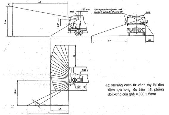
Figure 1 - Driver visibility
Schedule 1 - Criteria for evaluating driver visibility
| No. | Criteria | Symbol | Value (m) |
| 1 | Length of blind spot | L1 | ≤ 3,0 |
| 2 | The leftmost limit of road segment obstructed by the pole | L2 | ≤ 7,0 |
| 3 | Distance from projection of the vehicle’s cabin and projection of K on the road (K is placed on the overhead visibility line, 5 m from the road surface) | L3 | ≤ 10,0 |
| 4 | Width of road segment obscured by the pole | B1 | ≤ 1,2 |
| 5 | Distance from the leftmost limit of obscured road segment to the left side of the vehicle | B2 | ≤ 2,0 |
| 6 | Distance from the rightmost limit of obscured road segment to the right side of the vehicle | B3 | ≤ 6,0 |
2.4.5. If the driver’s compartment is open top, protective measures must be taken to protect driver from breeze, rain, and dust.
2.4.6. If the driver’s compartment is separate or not leading to passenger’s compartment, driver’s compartment must have 2 exits located on different sides of the vehicle; if one of the exits is a window, regulations on emergency exit windows under 2.5.4 must be complied with.
2.5. Passenger’s compartment
2.5.1. Passenger’s compartment must be designed to ensure safety for passengers.
2.5.2. Effective area for each standing passenger must not be lower than 0,125 m2. Space for standing passengers shall be the space where seats are not located on floor area for passengers mentioned under 2.1.6 and must satisfy the following requirements:
Minimum effective height is 1800 mm;
Minimum effective width is 300 mm;
Handrails and grips are equipped for standing passengers.
2.5.3. Service door and stairs
2.5.3.1. Minimum effective dimensions of service doors are specified under Schedule 2.
2.5.3.2. Number of service doors:
a) Minimum number of service doors is specified under Schedule 3;
b) In case of articulated vehicles, minimum number of service doors of the front car is 2, minimum number of service doors of the back car is 1;
c) If double doors serve as service doors, each double door is equivalent to 2 single doors for the purpose of calculating service doors;
d) In case of double deck vehicles:
- Each stair is considered an access passage of the second deck;
- If the number of passengers occupying the second deck exceeds 50, at least 2 stairs or at least 1 stair and 1 emergency exit stair are required.
Schedule 2 - Minimum effective dimensions of service doors
| Number of passengers | Minimum effective dimension of door (mm) | |||
| Single door | Double door | |||
| Width (1) | Height | Width (1) | Height | |
| 17 to 40 passengers | 650 | 1700 | 1200 | 1700 |
| More than 40 passengers | 650 | 1800 | 1200 | 1800 |
| Note: (1) This dimension can be reduced by 100 mm if it is measured at the furthest protruding point of the door handle. | ||||
Schedule 3: Minimum number of service doors
| Number of passengers | 17 to 45 | 46 to 90 | Above 90 |
| Minimum number of service doors | 1 | 2 | 3 |
2.5.3.3. Other requirements
a) Service doors must be positioned on the sides of the vehicles;
b) At least one service door must be located on the starboard side and on the front half of the vehicle (except Bus Rapid Transit - BRT or similar modes of transport);
c) At least one door at the back of the vehicle or the sides of the vehicle is allowed to be designed specifically for wheelchair accessibility;
d) Service doors must be opened easily from inside of the vehicle, outside of the vehicle, and prevented from being opened when they have been locked; designed to ensure safety for passengers in normal use conditions.
2.5.3.4. Requirements for coupling sections of articulated vehicles:
a) The gap(1) that is not covered and located between floor of a car and floor of the turn table or similar mechanisms must be:
- No more than 1 cm: When all wheels are on the same plane;
- No more than 2 cm: When wheels of the axle adjacent to the coupling are parked 15 cm above other axles;
Note:(1) Is measured when the vehicle is not loaded and parked on horizontal surface
b) Difference in height between floor of a car and floor of the turn table measured at the coupling must be:
- No more than 2 cm: When all wheels are on the same plane;
- No more than 3 cm: When wheels of the axle adjacent to the coupling are parked 15 cm above other axles.
2.5.4. Emergency door
Vehicles must be equipped with emergency doors; service doors are not considered emergency doors. Emergency doors must meet the following requirements:
2.5.4.1. Minimum dimensions of emergency doors:
Width x height = 550 mm x 1200 mm.
2.5.4.2. Emergency doors must be opened with ease from the inside or outside when the vehicles are not moving. Emergency doors must be locked from the outside as long as they must also be open from the inside via regular mechanisms in any circumstance.
2.5.4.3. Emergency doors must not be sliding door or powered doors (electricity, pneumatic, etc.).
2.5.4.4. All mechanisms and equipment required to open emergency doors from the outside (emergency doors on the first deck in regard to a double-deck vehicle) must be within a height of 1000 mm to 1500 mm from the parking surface and no more than 500 mm from the emergency doors that they control. All mechanisms and equipment required to open emergency doors from the inside must be within a height of 1000 mm to 1500 mm from the floor of the vehicle or the closest step and no more than 500 mm away from the emergency doors that they control. This does not apply to mechanisms and equipment located in driver’s compartment.
2.5.4.5. Emergency doors on the sides of automobiles must be hinged on the side that is closest to the front of the vehicle; emergency doors must be out-swinging doors. Braces, chains, or other restraint devices are allowed if they do not obstruct the opening of emergency doors and emergency doors must still be able to open to at least 100o. If inspection gauges can easily reach emergency doors from access passages, the minimum angle of 100o is not mandatory.
2.5.4.6. Emergency doors must be protected from unintentional opening. This requirement does not apply to emergency doors that are automatically locked when the vehicles move at a velocity greater than 5 km/h.
2.5.4.7. Audible warning devices are required to inform drivers about emergency doors that have not been fully closed. These warning devices must be engaged when door handles or hooks are moved from designated positions.
2.5.4.8. Emergency windows must have minimum area of 0,4 m2 and must be able to fit a rectangle of 500 mm in height and 700 mm in width (in this case, emergency windows are considered emergency doors).
2.5.4.9. Emergency windows at the back of the vehicle must satisfy requirements under 2.5.4.8. or must be able to fit a rectangle of 350 mm in height and 1550 mm in width with round corners where radius curvature does not exceed 250 mm (in this case, emergency windows at the back of the vehicle are considered emergency doors).
2.5.4.10. Hinged emergency windows must be out-swinging.
2.5.4.11. Emergency windows must be opened easily from the inside and outside by appropriate mechanisms or must be made of highly durable glass.
2.5.4.12. Emergency windows that can be locked from the outside must be opened easily from the inside at any time.
2.5.4.13. In regard to top-hinged emergency windows, appropriate mechanisms for holding doors in completely opened state without obstructing access passages to emergency windows from the inside or outside of the vehicle.
2.5.4.14. The height from the lower edge of emergency windows on the side of the vehicle to the vehicle floor below the emergency windows (excluding wheel sections) must not exceed 1200 mm and must not be lower than 650 mm in case of hinged emergency windows or 500 mm in case of emergency windows made of highly durable glass.
In case of hinged emergency windows, height of the lower edge can be reduced to 500 mm if the windows are equipped with protective measures up to a height of 650 mm in order to prevent falling hazards. In regard to these protected windows, dimensions of window sections above the protected sections must not be lower than the minimum dimensions applicable to emergency windows.
2.5.4.15. Minimum number of emergency doors is specified under Schedule 4.
Schedule 4 - Minimum number of emergency doors
| Number of passengers(1) | 17 ÷ 30 | 31 ÷ 45 | 46 ÷ 60 | 61 ÷ 75 | 76 ÷ 90 | > 90 |
| Minimum emergency doors(2) | 4 | 5 | 6 | 7 | 8 | 9 |
| Note: (1) In regard to double deck vehicles/articulated vehicles, number of passenger means the number of passengers, drivers, and attendants on each deck/car. (2) Service doors are not considered emergency doors; Emergency doors in this schedule include emergency doors and emergency windows. | ||||||
2.5.4.16. Toilets, kitchens, liquor bars (if any), areas connecting cars shall not be included when calculating number of emergency doors as described above.
2.5.4.17. Double windows or windows of multiple compartments are equivalent to 2 emergency windows as long as they are qualified for emergency windows.
2.5.4.18. Each emergency door and emergency window must be notified by the phrase “CỬA THOÁT KHẨN CẤP” or “EMERGENCY EXIT” or both together with necessary instructions. Glass breakers must be provided in areas close to emergency windows made of highly durable glass.
2.5.4.19. Access passages to emergency doors and emergency windows must meet requirements under QCVN 09:2015/BGTVT.
2.5.5. Seat other than driver’s seat
2.5.5.1. Seats must be firmly installed in order to ensure safety for seated passengers in normal operation.
2.5.5.2. Seat dimensions:
Width: ≥ 400 mm
Depth: ≥ 350 mm
Height (H): 400 ÷ 500 mm
Seats above fender and engine block can have its height reduced to 350 mm as long as passenger comfort is guaranteed.
2.5.5.3. Distance from the back of the seat-back of the front seat to the front of the seat-back of the next seat behind (L) must not be lower than 630 mm.
2.5.5.4. Distance between the front of seat-back of 2 facing seats (L0) must not be lower than 1250 mm.
Distances are specified under Schedule 5 and illustrated under Figure 2.
Schedule 5 - Distances between seats
Unit: mm
| Lmin | L0 min | H |
| 630 | 1250 | 400 ÷ 500 |
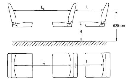
Figure 2 - Distance between seats
2.5.6. Gangway
- Width: ≥ 400 mm
- Height from floor to ceiling, measured on gangway:
First deck: ≥ 1800 mm
Second deck: ≥ 1680 mm
- Slope of gangway: ≤ 8 %.
- The space along gangway must be designed to facilitate movement of a gauge consisting of 2 concentric cylinders connected by a cone. Dimensions of the cylinders are described under Figure 3.
If the vehicle is allowed to be fitted with foldable seats along gangway, the gauge shall be deployed when the seats are extended if the seats do not automatically fold when unused or when the seats are folded if the seats automatically fold when unused.
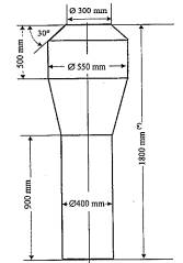
(*) This dimension shall be 1680 mm in regard to gauge deployed on the second deck of a double deck vehicle
Figure 3 - Gangway measurement gauge
2.5.7. Floor
Vehicle floor must be made of non-slip materials.
2.5.8. Steps
2.5.8.1. Surface of the steps must be rough or covered with materials that have a lot of friction.
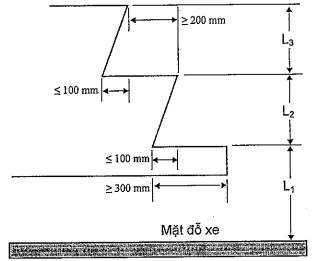
2.5.8.2. Maximum riser height and tread depth of service doors, stairs, emergency doors, and inside the vehicle are illustrated under Figure 4 and described under Schedule 6.
![]()
Figure 4 - Riser height and tread depth
Schedule 6 - Permissible riser height and tread depth
Unit: mm
| The first step (from the parking surface) | Service door | Maximum riser height (L1) | 400 | |
| Minimum tread depth | 300(1) | |||
| Emergency doors | Maximum riser height (L1) | First deck | 850(2) | |
| Second deck | 1500 | |||
| Minimum tread depth | 300 | |||
| Other steps | Maximum riser height (L2, L3) | 250(3) | ||
| Minimum riser height (L2, L3) | 120 | |||
| Minimum effective tread depth(4) | 200 | |||
| Note: (1) 200 in case of vehicle with capacity of up to 40 passengers; (2) 700 in case of a single-deck vehicle; (3) 300 in case of access steps of doors positioned behind the last axle; (4) Effective depth is determined by the surface area on which a person can rest their foot on without slipping; Riser height from the parking surface is determined when the vehicle is not loaded; Riser height (L2, L3) of each step may vary. | ||||
2.5.8.3. Riser heights (L1, L2, L3) under Schedule 6 do not apply to service doors designed to fit infrastructures at stops and allow passengers to embark and disembark on separate lane.
2.5.8.4. Width and surface of steps must be large enough so that when a rectangular gauge of 400 mm x 300 mm is placed on the first surface and a rectangular gauge of 400 mm x 200 mm is placed on other steps, part of the gauge that protrudes from the steps must not exceed 5% of the gauge area. In regard to double doors, each half of access steps must satisfy this requirement.
2.5.8.5. Slope of steps in any direction must not exceed 5%.
2.5.8.6. In case of double doors, steps of each half of access passages must be considered separate steps.
2.5.9. Grips and handrails
2.5.9.1. Grips and handrails must be sturdy to allow passengers to firmly, safely grip. The handle of grips must have minimum length of 100 mm; dimensions of cross sections of grips must range from 20 mm to 45 mm. Suspension rope is considered a grip if they are appropriately installed.
2.5.9.2. Grips and handrails must be adequately equipped, reasonably distributed, and located at a height ranging from 800 mm to 1800 mm without affecting movement of passengers in the vehicle and when embarking, disembarking the vehicle.
2.5.9.3. Both sides of service doors must be fitted with grips and handrails. In regard to a double door, a grip pole can be positioned in the middle.
2.5.9.4. Both sides of doors must be fitted with guardrails which separate passenger’s seats from access areas. Height of guardrails from the floor must not be lower 600 mm.
2.5.9.5. Stair must be fitted with guardrails and grips.
2.5.9.6. Coupling sections (in case of articulated vehicles) must be fitted with handrails and/or guardrails/partitions to prevent passengers from accessing:
Floor section with uncovered gap and not satisfactory to requirements under 2.5.3;
Floor section not intended for passenger transport;
Areas where movement of the sides of the coupling sections can cause danger to passengers;
2.5.9.7. Guardrails are required in areas close to the front windshield on the second deck of double-deck vehicle. Height of the upper side of this guardrail must be within 800 mm to 900 mm from the floor. The guardrails must satisfy requirements relating to guardrails under QCVN 09:2015/BGTVT and this Circular document.
2.5.10. Lighting in passenger’s compartment
Passenger’s compartments must be fitted with lights to illuminate:
- Gangway;
- All steps;
- If a double-deck vehicle is open top, at least one light must be installed as close as possible to the top of the stairs leading to the second deck.
2.5.11. Passenger’s disembarkation signal
Passenger’s compartment must be fitted with devices that inform drivers about passengers wishing to disembark or two-way communication devices between drivers and passengers if passenger’s compartment is separate from driver’s compartment.
2.5.12. Airtightness of passenger’s compartment and driver’s compartment
Vehicles must be inspected for airtightness in order to prevent water from leaking into the vehicles. The floor must not allow passage smoke and dust from engine block and from beneath the floor into the vehicle.
This requirement does not apply to open top deck.
2.6. Requirements for protective measures for open top vehicles
An open top vehicle must meet the following requirements:
2.6.1. A board going along the vehicle’s width and covering the front of open top section of the vehicle is required. Height of the board must not be lower than 1400 mm from the floor.
2.6.2. A guardrail going along the sides and the rear of the open top section of the vehicle is required. The height of the side guardrails must not be lower than 1100 mm and height of the rear guardrails must not be lower than 12 mm from the floor. Side and rear guardrails must be accompanied by continuous glass panels located at a minimum height of 700 mm from the floor and handrails that meet the following requirements:
2.6.2.1. Cross sections of the handrails must not be lower than 20 mm or larger than 45 mm at any point.
2.6.2.2. Gaps between adjacent handrails and gaps between handrails and adjacent glass panels must not exceed 200 mm.
2.6.2.3. They must be firmly attached to the vehicle structures.
2.6.2.4. Doors of exits must be considered parts of these protective structures and must satisfy the aforementioned requirements.
2.6.3. Visibility and communication aid
In case of open top vehicles, drivers must be provided with visibility aid such as mirrors, periscopes, or video recorders and monitors in order to monitor activities of passengers in open top areas and communication devices to allow drivers to communicate with these passengers.
2.7. Other requirements
2.7.1. Rear-view mirrors
2.7.1.1. Rear-view mirrors must satisfy requirements under the QCVN 09:2015/BGTVT.
2.7.1.2. In addition, rear-view mirrors or other devices installed inside vehicles are required to allow drivers to observe main section of passenger’s compartment and door areas.
2.7.2. Windshield, side glass, rear glass, roof glass used on any deck of vehicles must satisfy requirements under the QCVN 09:2015/BGTVT.
2.7.3. Tyres and headlight of vehicles must satisfy requirements under the QCVN 09:2015/BGTVT.
2.7.4. Onboard heat sources
Provide thermal insulation for all heat sources which cause safety loss to fuel system, electrical system, and other flammable components.
2.7.5. Fire extinguishers and first-aid kits must satisfy requirements under the QCVN 09:2015/BGTVT.
2.7.6. Regulations on environmental protection
Emission, noise, and refrigerant limits in air conditioners of vehicles must satisfy requirements under the QCVN 09:2015/BGTVT.
3. REGULATIONS ON MANAGEMENT
3.1. Testing and examination methods
Testing and examination methods: Vehicles must be tested and examined in accordance with Circular No. 30/2011/TT-BGTVT dated April 15, 2011 of the Minister of Transport and Circular No. 54/2014/TT-BGTVT dated October 20, 2014 of the Minister of Transport.
Technical dossiers and testing samples: Manufacturing facilities, importing organizations and individuals are responsible for providing technical dossiers and samples for testing in accordance with applicable regulations of the Ministry of Transport.
3.2. Test report
Testing facilities must produce test reports that include details under this document.
4. ORGANIZING IMPLEMENTATION
4.1. The Vietnam Register is responsible for the implementation of this document during technical safety and environmental protection inspection of urban buses.
4.2. Roadmap for implementation
4.2.1. This Regulation shall apply to manufactured, assembled vehicles for which the certification for technical quality, safety and environmental protection has been issued and imported vehicles which have been examined and issued with certification for technical quality, safety and environmental protection before the effective date hereof after 18 months from the effective date hereof.
4.2.2. This Regulation shall apply to manufactured, assembled vehicles for which the certification for technical quality, safety, and environmental protection is issued for the first time and imported vehicles which have not been examined nor issued with the certification for technical quality, safety, and environmental protection from January 1, 2017.
4.2.3. Requirements pertaining to testing of parts and examination, testing or exemption from testing of vehicle emission shall conform to the QCVN 09:2015/BGTVT.
4.2.4. Requirements pertaining to refrigerants in vehicle air conditioners (see 2.7.6) shall be implemented in accordance with the Government's roadmap for reducing and eliminating ozone depleting substances.
4.3. If Regulations referred to under this document are amended or replaced, the new versions shall prevail. Roadmap for implementation shall conform to roadmaps specified under respective Regulations.
APPENDIX
TURNING RADIUS
Vehicles must be able to turn in both directions within a plane limited by 2 concentric circles (forming a napkin-ring shape) where radius of the outer circular is 12,5 m and radius of the inner circle is 5,3 m (see Figure 5).
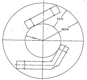
Figure 5 - Turning radius
When a vehicle moves in a straight line into the napkin-ring shape, any part of the vehicle must not protrude from the vertical plane limited by the outer ring by more than 0,6 m (see Figure 6a and Figure 6b).
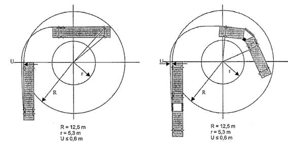
| Figure 6a - Turning radius of rigid vehicle | Figure 6b - Turning radius of articulated vehicle |