
 Tiếng Việt
- 1 Circular No. 30/2011/TT-BGTVT of April 15, 2011, on the environment protection and technical safety quality inspection in motor vehicle production and assembly
- 2 Circular No. 45/2012/TT-BGTVT of October 23, 2012, on the inspection of the technical quality, safety, and environment protection in the p and assembly of motorbikes
- 3 Circular No. 31/2011/TT-BGTVT of April 15, 2011, regulating the inspection of quality on technical safety and environmental protection for imported motor vehicles
- 4 Circular No. 55/2014/TT- BGTVT dated October 20, 2014, amending Circular No. 31/2011/TT-BGTVT stipulating the inspection of technical safety, quality and environmental protection for imported motor vehicles
- 5 Circular No. 54/2014/TT-BGTVT dated October 20, 2014, amending Circular No. 31/2011/TT-BGTVT stipulating the inspection of technical safety, quality and environmental protection in manufacturing and assembling motor vehicles
- 6 Circular No. 03/2018/TT-BGTVT dated January 10, 2018 technical and environmental safety inspection of imported motor vehicles regulated by Decree 116/2017/ND-CP
- 7 Circular No. 25/2019/TT-BGTVT dated 05th of July, 2019 on the technical safety and environmental safety inspection in automobile manufature and assembly
| THE MINISTRY OF TRANSPORT | THE SOCIALIST REPUBLIC OF VIETNAM |
| No. 26/2019/TT-BGTVT | Hanoi, August 01, 2019 |
Pursuant to the Law on Standards and Technical Regulations dated June 29, 2006;
Pursuant to the Government’s Decree No. 127/2007/ND-CP dated August 01, 2007 on elaboration of the Law on Standards and Technical Regulations;
Pursuant to the Government’s Decree No. 12/2017/ND-CP dated February 10, 2017 defining the functions, tasks, powers and organizational structure of the Ministry of Transport;
At the request of the Director of the Department of Science and Technology and the Director of Vietnam Register,
The Minister of Transport hereby promulgates a Circular on National technical regulation on urban buses designed for easy access for disabled people and 05 National technical regulations on spare parts and accessories for automobiles, motorcycles and mopeds.
Article 1. 06 National technical regulations are promulgated together with this Circular:
...
...
...
Mọi chi tiết xin liên hệ: ĐT: (028) 3930 3279 DĐ: 0906 22 99 66
Code: QCVN 33: 2019/BGTVT.
2. National technical regulation on lead - acid, Lithium - ion batteries of motorcycles and mopeds;
Code: QCVN 47: 2019/BGTVT.
3. National technical regulation on motor vehicle structure to the prevention of fire risks;
Code: QCVN 52: 2019/BGTVT.
4. National technical regulation on the burning behaviour of materials used in the interior structure of certain categories of motor vehicles;
Code: QCVN 53: 2019/BGTVT.
5. National technical regulation on urban buses designed for easy access for disabled people.
Code: QCVN 82: 2019/BGTVT.
...
...
...
Mọi chi tiết xin liên hệ: ĐT: (028) 3930 3279 DĐ: 0906 22 99 66
Code: QCVN 91: 2019/BGTVT.
1. This Circular comes into force from September 15, 2019.
2. This Circular annuls:
a) Clause 2 Article 1 of the Circular No. 57/2011/TT-BGTVT;
b) The Circular No. 40/2013/TT-BGTVT;
c) Clause 3 Article 1 of the Circular No. 52/2012/TT-BGTVT;
d) Clause 2 Article 1 of the Circular No. 82/2015/TT-BGTVT;
e) The Circular No. 62/2014/TT-BGTVT.
...
...
...
Mọi chi tiết xin liên hệ: ĐT: (028) 3930 3279 DĐ: 0906 22 99 66
PP. THE MINISTER
THE DEPUTY MINISTER
Le Dinh Tho
NATIONAL TECHNICAL REGULATION ON MIRRORS FOR AUTOMOBILES
Foreword
QCVN 33:2019/BGTVT is prepared by Vietnam Register, appraised by the Department of Science and Technology and promulgated by the Ministry of Transport together with the Circular No. 26/2019/TT-BGTVT dated August 01, 2019.
QCVN 33:2019/BGTVT replaces QCVN 33:2011/BGTVT.
...
...
...
Mọi chi tiết xin liên hệ: ĐT: (028) 3930 3279 DĐ: 0906 22 99 66
NATIONAL TECHNICAL REGULATION ON MIRRORS FOR AUTOMOBILES
1.1. Scope
1.1.1. This Regulation provides for specifications and test methods for mirrors and camera-monitor systems for automobiles, as defined in TCVN 6211 “Road vehicles - Types - Terms and definitions”.
1.1.2. This Regulation does not apply to mirrors and camera-monitor systems fitted to automobiles serving national defense and security purposes and other devices able to present information about the indirect field of vision to the driver as specified in Annex A to this Regulation.
1.2. Regulated entities
This Regulation applies to establishments manufacturing and importing mirrors and camera-monitor systems; establishments manufacturing, assembling and importing automobiles and organizations related to management, testing and technical safety and quality inspection of mirrors and camera-monitor systems for automobiles.
1.3. Definitions
...
...
...
Mọi chi tiết xin liên hệ: ĐT: (028) 3930 3279 DĐ: 0906 22 99 66
1.3.2. “Camera-monitor system (CMS)” means a device for indirect vision as defined in Annex A to this Regulation, where the field of vision is obtained by means of a camera monitor combination as defined below:
a) Camera means a device that renders an image of the outside world and then converts this image into a signal (e.g. video signal).
b) “Monitor” means a device that converts a signal into images that are rendered into the visual spectrum.
1.3.3. “Field of vision” means the section of the tri-dimensional space which is monitored with the help of a mirror or camera-monitor system. Unless otherwise stated, this is based on the vision on ground level by driver’s eyes in the normal driving position.
1.3.4. “Interior mirror” means a device which can be fitted in the passenger compartment of a vehicle.
1.3.5. “Exterior mirror” means a device which can be mounted on the external surface of a vehicle.
1.3.6. “Surveillance mirror” means a mirror other than the ones defined in paragraph 1.3.1. above which can be fitted to the inside or outside of the vehicle in order to provide fields of vision other than those specified in Annex A to this Regulation.
1.3.7. “Mirror type”: rear-view mirrors may be deemed to be of the same type if they are of the same brand, are manufactured by the same manufacturer and on the same production line and do not differ in respect of the following main characteristics:
a) The dimensions and radius of curvature of the mirror reflecting surface;
...
...
...
Mọi chi tiết xin liên hệ: ĐT: (028) 3930 3279 DĐ: 0906 22 99 66
1.3.8. “Camera-monitor type”: camera-monitor systems are considered being of the same type if they are manufactured by the same manufacturer and on the same production line and do not differ in respect of the following main characteristics:
a) Design of the device inclusive, if pertinent, the attachment to the bodywork;
b) The class, the field of view, the magnification and resolution.
1.3.9. “Average of the radii of curvature (r)” means the average of the radii of curvature measured over the reflecting surface, in accordance with the method described in C.2 Annex C to this Regulation.
1.3.10. “Principal radii of curvature at one point on the reflecting surface (ri)” means the values obtained with the apparatus defined in Annex C to this Regulation, measured on the arc of the reflecting surface passing through the centre of this surface parallel to the segment “b”, as defined in paragraph 2.1.2 of this Regulation and on the arc perpendicular to this segment.
1.3.11. “Radius of curvature at one point obtained on the reflecting surface (rp)” means the arithmetical average of the principal radii of curvature ri and ri'.
![]()
1.3.12. “Centre of the reflecting surface” means the centre of the visible area of the reflecting surface.
1.3.13. “Radius of curvature of the constituent parts of the mirror (c)” means the radius “c” of the arc of the circle which most closely approximates to the curved form of the part in question.
...
...
...
Mọi chi tiết xin liên hệ: ĐT: (028) 3930 3279 DĐ: 0906 22 99 66
a) Class I: "Rear-view device", giving the field of vision defined in Figure A.1 Annex A to this Regulation.
b) Class II and III: "Main rear-view device", giving the field of vision defined in Figures A.1 and A.3 Annex A to this Regulation.
c) Class IV: "Wide-angle view device", giving the field of vision defined in Figure A.4 Annex A to this Regulation.
d) Class V, "Close-proximity view device", giving the field of vision defined in Figure A.5 Annex A to this Regulation.
dd) Class VI, "Front-view device", giving the field of vision defined in Figure A.6 Annex A to this Regulation.
1.3.15. “Mirror and CMS dual function system (CMS)” means a CMS of Class I in which a monitor complying with this regulation is placed behind a semi-transparent mirror complying with this regulation. The monitor is visible in the CMS mode.
2.1. Mirrors
2.1.1. General requirements
...
...
...
Mọi chi tiết xin liên hệ: ĐT: (028) 3930 3279 DĐ: 0906 22 99 66
2.1.1.2. All mirrors shall be adjustable.
2.1.1.3. Radius of curvature “c”
a) Mirrors Classes II to VI:
The edge of the reflecting surface shall be enclosed in a protective housing which, on its perimeter, shall have a value “c” greater than or equal to 2.5 mm at all points and in all directions. If the reflecting surface projects beyond the protective housing, the radius of curvature “c” on the edge of the projecting part shall be not less than 2.5 mm and the reflecting surface shall return into the protective housing under a force of 50 N applied to the point of greatest projection, relative to the protective housing, in a direction perpendicular to the reflecting surface.
b) Mirrors Class I:
In cases, where the edge of the reflecting surface is enclosed in a protective housing, the radius of curvature “c” on its perimeter shall be not less than 2.5 mm at all points and in all directions.
2.1.1.4. When the mirror is mounted on a plane surface, all parts, irrespective of the adjustment position of the device, including those parts remaining attached to the support after the test provided for in Annex D to this Regulation, which are in potential, static contact with a sphere either 165 mm in diameter in the case of a Class I mirror or 100 mm in diameter in the case of a Class II to VI mirror, shall have a radius of curvature “c” of not less than 2.5 mm.
Edges of fixing holes or recesses of which the diameter or longest diagonal is less than 12 mm are exempt from the radius requirements above provided that they are blunted.
2.1.1.5. The device for the attachment of mirrors to the vehicle shall be so designed that a cylinder, having as its axis the axis, or one of the axes, of pivot or rotation which ensures deflection of the mirror in the direction of impact concerned, passes through at least part of the surface to which the device is attached.
...
...
...
Mọi chi tiết xin liên hệ: ĐT: (028) 3930 3279 DĐ: 0906 22 99 66
2.1.1.7. In the case of those parts of Class I mirrors which are made of a material with a Shore A hardness of less than 50 and which are mounted on a rigid support, the requirements of paragraphs 2.1.1.3. and 2.1.1.4. above shall only apply to the support.
2.1.2. Dimensions
2.1.2.1. Mirrors Class I
The dimensions of the reflecting surface shall be such that it is possible to inscribe thereon a rectangle one side of which is 40 mm and the other “a” mm in length, where
 (mm)
(mm)
and “r” is the radius of curvature (mm).
2.1.2.2. Mirrors Classes II and III
2.1.2.2.1. The dimensions of the reflecting surface shall be such that it is possible to inscribe therein:
a) A rectangle 40 mm high the base length of which, measured in millimetres, has the value “a”, and
...
...
...
Mọi chi tiết xin liên hệ: ĐT: (028) 3930 3279 DĐ: 0906 22 99 66
2.1.2.2.2. The minimum values of "a" and "b" are given in the table below:
Table 1 - Minimum values of “a” and “b”
Unit: mm
Class of mirror
a
b
II

200
...
...
...
Mọi chi tiết xin liên hệ: ĐT: (028) 3930 3279 DĐ: 0906 22 99 66

70
r: the radius of curvature.
2.1.2.3. Mirrors Class IV
The contours of the reflecting surface shall be of simple geometric form and its dimensions such that it provides, if necessary in conjunction with a Class II exterior mirror, the field of vision specified in A.4 Annex A to this Regulation.
2.1.2.4. Mirrors Class V
The contours of the reflecting surface shall be of simple geometric form and its dimensions such that the mirror provides the field of vision specified in A.5 Annex A to this Regulation.
2.1.2.5. Mirrors Class VI
The contours of the reflecting surface shall be of simple geometric form and its dimensions such that the mirror provides the field of vision specified in A.6 Annex A to this Regulation.
...
...
...
Mọi chi tiết xin liên hệ: ĐT: (028) 3930 3279 DĐ: 0906 22 99 66
2.1.3.1. The reflecting surface of a mirror shall be either flat or spherically convex.
2.1.3.2. Value of “r” for spherical mirrors shall not be less than:
a) 1,200 mm for mirrors Class I.
b) 1,200 mm for Class II and III mirrors.
c) 300 mm for Class IV and V mirrors.
d) 200 mm for mirrors Class VI.
2.1.3.3. Differences between the radii of curvature of mirrors:
a) The difference between ri or r'i, and rp at each reference point shall not exceed 0.15 r;
b) The difference between any of the radii of curvature (rP1, rP2, rP3) and r shall not exceed 0.15 r;
...
...
...
Mọi chi tiết xin liên hệ: ĐT: (028) 3930 3279 DĐ: 0906 22 99 66
2.1.3.4. The value of the normal coefficient of reflection, as determined according to the method described in Annex B to this Regulation, shall be not less than 40%. In the case of reflecting surfaces with a changeable degree of reflection, the “day” position shall allow the colours of the signals used for road traffic to be recognized. The value of the normal coefficient of reflection in the “night” position shall be not less than 4%.
2.1.4. Impact and bending of the holder
2.1.4.1. Mirrors shall be subjected to the tests described in Annex D and Annex E to this Regulation to determine their behavior under impact on the reflecting surface and bending of the protective housing.
The tests shall not be required in the case of mirrors Classes V and VI.
2.1.4.2. The mirror shall not break during the tests. However, breakage of the reflecting surface of the mirror will be allowed if the mirror is made of safety glass or the following condition is fulfilled:
The fragments of glass still adhere to the back of the housing or to a surface firmly attached to the housing; partial separation of the glass from its backing is admissible provided that this does not exceed 2.5 mm on either side of the cracks. It is permissible for small splinters to become detached from the surface of the glass at the point of impact.
2.1.4.3. In the case of mirrors, should the mounting of the mirror break during the impact tests for mirrors stuck to the windscreen, the part remaining shall not project beyond the base by more than 10 mm and the configuration remaining after the test shall satisfy the conditions laid down in paragraph 2.1.1.3. of this Regulation.
2.1.4.4. The test described in Annex D to this Regulation shall not be required in the case of any mirror of which no part is less than 2 m from the ground, regardless of the adjustment position, when the vehicle is under a load corresponding to its technically permissible maximum laden mass.
This derogation also applies to the attachments of devices for indirect vision (attachment plates, arms, swivel joints, etc.) which are situated less than 2 m from the ground and which do not project beyond the overall width of the vehicle, measured in the transverse plane passing through the lowest mirror attachments or any other point forward of this plane if this configuration produces a greater overall width.
...
...
...
Mọi chi tiết xin liên hệ: ĐT: (028) 3930 3279 DĐ: 0906 22 99 66
Where advantage is taken of this derogation, the arm shall be indelibly marked with the symbol 2∆m and the type approval certificate shall be endorsed to this effect.
2.2. Camera-monitor systems (CMS)
2.2.1. General requirements
2.2.1.1. CMS shall bear the trade name or mark of the manufacturer; this marking shall be clearly legible and be indelible.
2.2.1.2. If adjustment by the user is needed, the CMS shall be adjustable without the use of tools.
2.2.1.3. When the devices of the camera-monitor system are mounted in the position recommended by the manufacturer for normal driving, all parts, irrespective of the adjustment position of the device which are in potential, static contact with a sphere either 165 mm in diameter in the case of a CMS or parts of CMS installed inside the vehicle or 100 mm in diameter in the case of a CMS or parts of CMS installed outside the vehicle, shall have a radius of curvature “c” of not less than 2.5 mm.
2.2.1.4. Edges of fixing holes or recesses of which the diameter or longest diagonal is less than 12 mm are exempt from the radius requirements of paragraph 2.2.1.3 above provided that they are blunted.
2.2.1.5. For parts of the camera and the monitor which are made of a material with a Shore A hardness of less than 60 and which are mounted on a rigid support, the requirements of paragraph 2.2.1.3 above shall only apply to the support.
2.2.2. Impact on CMS
...
...
...
Mọi chi tiết xin liên hệ: ĐT: (028) 3930 3279 DĐ: 0906 22 99 66
2.2.2.2. The test described in Annex D to this Regulation shall not be required in the case of the CMS of which no part is less than 2 m from the ground, regardless of the adjustment position, when the vehicle is under a load corresponding to its technically permissible maximum laden mass.
This derogation also applies to the attachments of the CMS (attachment plates, arms, swivel joints, etc.) which are situated less than 2 m from the ground and which do not project beyond the overall width of the vehicle, measured in the transverse plane passing through the lowest mirror attachments or any other point forward of this plane if this configuration produces a greater overall width.
In such cases, a description specifying that the CMS shall be mounted so as to conform to the above-mentioned conditions for the positioning of its attachments on the vehicle shall be provided.
Where advantage is taken of this derogation, the arm shall be indelibly marked with the symbol 2∆m.
2.2.2.3. The lens of the CMS shall not break during the tests described in Annex D to this Regulation.
3.1. Inspection and testing methods
Mirrors that are manufactured, assembled and imported shall undergo inspection and testing according to the Circular No. 30/2011/TT-BGTVT, Circular No. 54/2014/TT-BGTVT, Circular No. 31/2011/TT-BGTVT, Circular No. 55/2014/TT-BGTVT, Circular No. 03/2018/TT-BGTVT and Circular No. 25/2019/TT-BGTVT.
3.2. Technical documentation and test samples
...
...
...
Mọi chi tiết xin liên hệ: ĐT: (028) 3930 3279 DĐ: 0906 22 99 66
3.2.1. Technical documentation
3.2.1.1. A technical drawing of a mirror shall specify main dimensions and contain at least the following information:
a) Trade name or mark of the manufacturer, name or type of the mirror;
b) Installation location and instructions;
c) Hardness of the protective housing of the reflecting surface;
d) Radius of curvature of the reflecting surface;
dd) Reflection coefficient of the reflecting surface;
e) Radius of curvature of the edge of the reflecting surface;
g) Dimensions of the reflecting surface as specified in paragraph 2.2 of this Regulation.
...
...
...
Mọi chi tiết xin liên hệ: ĐT: (028) 3930 3279 DĐ: 0906 22 99 66
a) Technical specification of the CMS.
b) Operator’s manual.
c) A description of the camera monitor system which gives an explanation of the main function of the system, incl. drawings, pictures, block diagrams, etc.
d) A description of the location of the camera and the monitor in the vehicle (system overview).
dd) Name of manufacturer of camera, monitor and electronic control units.
e) Type of camera and monitor. Each unit shall be clearly and unambiguously identifiable (e.g. by marking for hardware and marking or software output for software content) to provide corresponding hardware and documentation association.
g) Explanation of the warning strategy and the safety concept, as defined by the manufacturer, covering at least the list of failures.
3.2.2. Test samples
04 test samples for each type of mirror to be tested.
...
...
...
Mọi chi tiết xin liên hệ: ĐT: (028) 3930 3279 DĐ: 0906 22 99 66
3.3. Test report
The testing facility shall prepare a test report containing the contents including the paragraphs set out in this Regulation.
3.4. Application of regulations
In the cases where any of the documents referred to in this Regulation is amended or replaced, the newest one shall apply.
4.1. Responsibility of Vietnam Register
Vietnam Register has the responsibility to organize the implementation of this Regulation.
4.2. Roadmap for implementation
4.2.1. This Regulation shall immediately apply from its effective date.
...
...
...
Mọi chi tiết xin liên hệ: ĐT: (028) 3930 3279 DĐ: 0906 22 99 66
a) They are not required to be tested again if no additional technical specifications are laid down under QCVN 33:2019/BGTVT;
b) 2 years from the effective date of this Regulation, they are required to undergo a test if any additional technical specification is laid down under QCVN 33:2019/BGTVT.
4.2.3. Regulations on CMS shall apply after 2 years from the effective date of this Regulation.
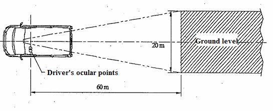
A.1. Class I rear-view device
The field of vision shall be such that the driver can see at least a 20 m wide, flat, horizontal portion of the road centred on the vertical longitudinal median plane of the vehicle and extending from 60 m behind the driver's ocular points (Figure A.1) to the horizon.
...
...
...
Mọi chi tiết xin liên hệ: ĐT: (028) 3930 3279 DĐ: 0906 22 99 66
A.2. Class II main rear-view device
A.2.1. Main rear-view device on the left side
The field of vision shall be such that the driver can see at least a 5 m wide, flat, horizontal portion of the road, which is bounded by a plane which is parallel to the median longitudinal vertical plane and passing through the outermost point of the vehicle on the driver's side of the vehicle and extends from 30 m behind the driver's ocular points to the horizon.
In addition, the road shall be visible to the driver over a width of 1 m, which is bounded by a plane parallel to the median longitudinal vertical plane and passing through the outermost point of the vehicle starting from a point 4 m behind the vertical plane passing through the driver's ocular points (see Figure A.2).
A.2.2. Main rear-view device on the right side
The field of vision shall be such that the driver can see at least a 5 m wide, flat, horizontal portion of the road, which is bounded on the passenger's side by a plane parallel to the median longitudinal vertical plane of the vehicle and passing through the outermost point of the vehicle on the passenger's side and which extends from 30 m behind the driver's ocular points to the horizon. In addition, the road shall be visible to the driver over a width of 1 m, which is bounded by a plane parallel to the median longitudinal vertical plane and passing through the outermost point of the vehicle starting from a point 4 m behind the vertical plane passing through the driver's ocular points (see Figure A.2).
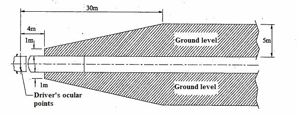
Figure A.2 - Class II fields of vision
A.3. Class III main rear-view device
...
...
...
Mọi chi tiết xin liên hệ: ĐT: (028) 3930 3279 DĐ: 0906 22 99 66
The field of vision shall be such that the driver can see at least a 4 m wide, flat, horizontal portion of the road, which is bounded by a plane parallel to the median longitudinal vertical plane and passing through the outermost point of the vehicle on the driver's side of the vehicle and extends from 20 m behind the driver's ocular points to the horizon.
In addition, the road shall be visible to the driver over a width of 1 m, which is bounded by a plane parallel to the median longitudinal vertical plane and passing through the outermost point of the vehicle starting from a point 4 m behind the vertical plane passing through the driver's ocular points (see Figure A.3).
A.3.2. Main rear-view device on the right side
The field of vision shall be such that the driver can see at least a 4 m wide flat, horizontal portion of the road which is bounded by a plane parallel to the median longitudinal vertical plane passing through the outermost point of the vehicle on the passenger's side and which extends from 20 m behind the driver's ocular points to the horizon.
In addition, the road shall be visible to the driver over a width of 1 m, which is bounded by a plane parallel to the median longitudinal vertical plane and passing through the outermost point of the vehicle starting from a point 4 m behind the vertical plane passing through the driver's ocular points (see Figure A.3).
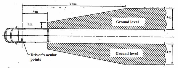
Figure A.3 - Class III fields of vision
A.4. Class IV wide-angle view device
A.4.1. Wide-angle view device on the left side
...
...
...
Mọi chi tiết xin liên hệ: ĐT: (028) 3930 3279 DĐ: 0906 22 99 66
In addition, the road shall be visible to the driver over a width of 4.5 m, which is bounded by a plane parallel to the median longitudinal vertical plane and passing through the outermost point of the vehicle starting from a point 1.5 m behind the vertical plane passing through the driver's ocular points (see Figure A.4).
A.4.2. Wide-angle view device on the right side
The field of vision shall be such that the driver can see at least a 15 m wide, flat, horizontal portion of the road, which is bounded by a plane parallel to the median longitudinal vertical plane of the vehicle and passing through the outermost point of the vehicle on the passenger's side and which extends from
In addition, the road shall be visible to the driver over a width of 4.5 m, which is bounded by a plane parallel to the median longitudinal vertical plane and passing through the outermost point of the vehicle starting from a point 1.5 m behind the vertical plane passing through the driver's ocular points (see Figure A.4).
Figure A.4 - Class IV fields of vision
A.5. Class V close-proximity view device
The field of vision shall be such that the driver can see a flat horizontal portion of the road along the side of the vehicle, bounded by the following vertical planes:
a) The plane parallel to the median longitudinal vertical plane of the vehicle which passes through the outermost point of the vehicle cab on the right side.
...
...
...
Mọi chi tiết xin liên hệ: ĐT: (028) 3930 3279 DĐ: 0906 22 99 66
c) To the rear, the plane parallel to the vertical plane passing through the driver's ocular points and situated at a distance of 1.75 m behind that plane.
d) To the front, the plane parallel to the vertical plane passing through the driver's ocular points and situated at a distance of 1 m in front of that plane. If the vertical transverse plane passing through the leading edge of the vehicle bumper is less than 1 m in front of the vertical plane passing through the driver's ocular points, the field of vision shall be limited to that plane (see Figures A.5a and A.5b).
Figure A.5a
Figure A.5b
Figure A.5 - Class V fields of vision
A.6. Class VI front-view device
The field of vision shall be such that the driver can see at least a flat horizontal portion of the road, which is bounded by:
...
...
...
Mọi chi tiết xin liên hệ: ĐT: (028) 3930 3279 DĐ: 0906 22 99 66
b) A transverse vertical plane 2 m in front of the plane defined in (a).
c) A longitudinal vertical plane parallel to the longitudinal vertical median plane going through the outermost side of the vehicle at the driver's side.
d) A longitudinal vertical plane parallel to the longitudinal vertical median plane 2 m outside the outermost side of the vehicle opposite to the driver's side.
The front of this field of vision opposite to the driver's side may be rounded off with a radius of 2,000 mm (see Figure A.6).
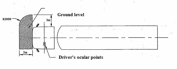
Figure A.6 - Class VI fields of vision
Test method for determining reflectivity
...
...
...
Mọi chi tiết xin liên hệ: ĐT: (028) 3930 3279 DĐ: 0906 22 99 66
B.1.1. CIE standard illuminate A: Colorimetric illuminate, respecting the full radiator at T68 = 2,855.6 K. B.1.2. CIE standard source A1: Gas-filled tungsten filament lamp operating at a correlated colour temperature of T68 = 2,855.6 K.
B.1.3. CIE 1931 standard colorimetric observer: Receptor of radiation whose colorimetric characteristics correspond to the spectral tristimulus values (see x(λ), y(λ), z(λ) table B.1).
B.1.4. CIE spectral tristimulus values: Tristimulus values of the spectral components of an equi energy spectrum in the CIE (XYZ) system.
B.1.5. Photopic vision: Vision by the normal eye when it is adapted to levels of luminance of at least several cd/m2.
B.2. Apparatus
B.2.1. General
The apparatus shall consist of a light source, a holder for the test sample, a receiver unit with a photodetector and an indicating meter (see Figure B.1), and means of eliminating the effects of extraneous light.
The receiver may incorporate a light-integrating sphere to facilitate measuring the reflectance of non-flat (convex) mirrors (see Figure B.2).
B.2.2. Spectral characteristics of light source and receiver
...
...
...
Mọi chi tiết xin liên hệ: ĐT: (028) 3930 3279 DĐ: 0906 22 99 66
B.2.2.2. The receiver shall have a photodetector with a spectral response proportional to the photopic luminosity function of the CIE (1931) standard colorimetric observer (see table B.1). Any other combination of illuminate-filter-receptor giving the overall equivalent of CIE standard illuminate A and photopic vision may be used. When an integrating sphere is used in the receiver, the interior surface of the sphere shall be coated with a matt (diffusive) spectrally nonselective white coating.
B.2.3. Geometrical conditions
The angle of the incident beam (Ɵ) should preferably be 0.44 ± 0.09 rad (25 ± 5°) from the perpendicular to the test surface and shall not exceed the upper limit of the tolerance (i.e. 0.53 rad or 30°).The axis of the receptor shall make an angle (Ɵ) with this perpendicular equal to that of the incident beam (see Figure B.1). The incident beam upon arrival at the test surface shall have a diameter of not less than 13 mm (0.5 inch). The reflected beam shall not be wider than the sensitive area of the photodetector, shall not cover less than 50% of such area, and as nearly as possible shall cover the same area segment as used during instrument calibration.
When an integrating sphere is used in the receiver section, the sphere shall have a minimum diameter of 127 mm (5 inch). The sample and incident beam apertures in the sphere wall shall be of such a size as to admit the entire incident and reflected light beams. The photodetector shall be so located as not to receive direct light from either the incident or the reflected beam.
B.2.4. Electrical characteristics of the photodetector-indicator unit
The photodetector output as read on the indicating meter shall be a linear function of the light intensity of the photosensitive area. Means (electrical and optical) shall be provided to facilitate zeroing and calibration adjustments. Such means shall not affect the linearity or the spectral characteristics of the instrument. The accuracy of the receptor indicator unit shall be within ±2% of full scale, or ±10% of the magnitude of the reading, whichever is the smaller.
B.2.5. Sample holder
The mechanism shall be capable of locating the test sample so that the axes of the source arm and receptor intersect at the reflecting surface.
B.3. Procedure
...
...
...
Mọi chi tiết xin liên hệ: ĐT: (028) 3930 3279 DĐ: 0906 22 99 66
Swing the receiver to a position directly on the axis of the light source. The reflectance value read directly from the indicating meter will correspond to a reflectance of 100%.
B.3.2. Indirect calibration method
The indirect calibration method is applicable in the case of instruments with fixed source and receiver geometry. A properly calibrated and maintained reflectance standard is required. This reference standard should preferably be a flat mirror with a reflectance value as near as possible to that of the test samples.
B.3.3. Flat mirror measurement
The reflectance of flat mirror samples can be measured on instruments employing either the direct or the indirect calibration method (see Figure B.1). The reflectance value is read directly from the indicating meter.
B.3.4. Convex mirror measurement
Measurement of the reflectance of convex mirrors requires the use of instruments which incorporate an integrating sphere in the receiver unit (see Figures B.2 and B.3). If the instrument-indicating meter indicates ne divisions with a standard mirror of E % reflectance, then, with a mirror of unknown reflectance, nx divisions will correspond to a reflectance of X %, in accordance with the formula:
![]()
...
...
...
Mọi chi tiết xin liên hệ: ĐT: (028) 3930 3279 DĐ: 0906 22 99 66
Figure B.1- Generalised reflectometer showing experimental set-ups for the two calibration methods
Figure B.2- Generalised reflectometer, incorporating an integrating sphere in the receiver
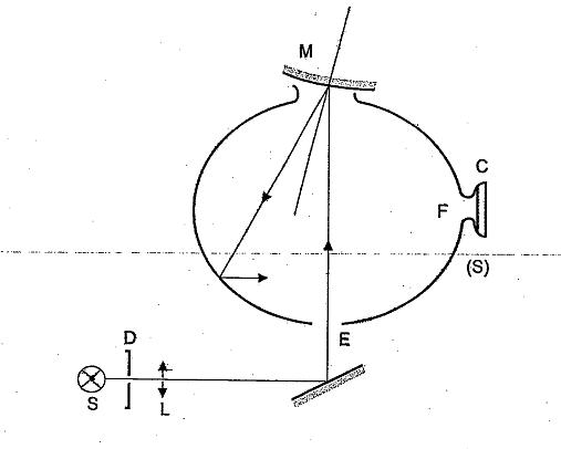
C
=
Receiver
D
=
...
...
...
Mọi chi tiết xin liên hệ: ĐT: (028) 3930 3279 DĐ: 0906 22 99 66
E
=
Window of entry
F
=
Window of measurement
L
=
Lens
...
...
...
Mọi chi tiết xin liên hệ: ĐT: (028) 3930 3279 DĐ: 0906 22 99 66
=
Object window
S
=
Light source
(S)
=
Integrating sphere
Figure B.3- Example of device for measuring the reflection factor of spherical mirrors
...
...
...
Mọi chi tiết xin liên hệ: ĐT: (028) 3930 3279 DĐ: 0906 22 99 66
Table B.1- Spectral tristimulus values for the CIE 1931 standard colorimetric observer(1)
(This table is taken from CIE publication 50 (45) (1970))
λ (nm)
x (2)
y (2)
z (2)
380
0,0014
0,0000
0,0065
...
...
...
Mọi chi tiết xin liên hệ: ĐT: (028) 3930 3279 DĐ: 0906 22 99 66
0,0042
0,0001
0,0201
400
0,0143
0,0004
0,0679
410
0,0435
...
...
...
Mọi chi tiết xin liên hệ: ĐT: (028) 3930 3279 DĐ: 0906 22 99 66
0,2074
420
0,1344
0,0040
0,6456
430
0,2839
0,0116
1,3856
...
...
...
Mọi chi tiết xin liên hệ: ĐT: (028) 3930 3279 DĐ: 0906 22 99 66
0,3483
0,0230
1,7471
450
0,3362
0,0380
1,7721
460
0,2908
...
...
...
Mọi chi tiết xin liên hệ: ĐT: (028) 3930 3279 DĐ: 0906 22 99 66
1,6692
470
0,1954
0,0910
1,2876
480
0,0956
0,1390
0,8130
...
...
...
Mọi chi tiết xin liên hệ: ĐT: (028) 3930 3279 DĐ: 0906 22 99 66
0,0320
0,2080
0,4652
500
0,0049
0,3230
0,2720
510
0,0093
...
...
...
Mọi chi tiết xin liên hệ: ĐT: (028) 3930 3279 DĐ: 0906 22 99 66
0,1582
520
0,0633
0,7100
0,0782
530
0,1655
0,8620
0,0422
...
...
...
Mọi chi tiết xin liên hệ: ĐT: (028) 3930 3279 DĐ: 0906 22 99 66
0,2904
0,9540
0,0203
550
0,4334
0,9950
0,0087
560
0,5945
...
...
...
Mọi chi tiết xin liên hệ: ĐT: (028) 3930 3279 DĐ: 0906 22 99 66
0,0039
570
0,7621
0,9520
0,0021
580
0,9163
0,8700
0,0017
...
...
...
Mọi chi tiết xin liên hệ: ĐT: (028) 3930 3279 DĐ: 0906 22 99 66
1,0263
0,7570
0,0011
600
1,0622
0,6310
0,0008
610
1,0026
...
...
...
Mọi chi tiết xin liên hệ: ĐT: (028) 3930 3279 DĐ: 0906 22 99 66
0,0003
620
0,8544
0,3810
0,0002
630
0,6425
0,2650
0,0000
...
...
...
Mọi chi tiết xin liên hệ: ĐT: (028) 3930 3279 DĐ: 0906 22 99 66
0,4479
0,1750
0,0000
650
0,2835
0,1070
0,0000
660
0,1649
...
...
...
Mọi chi tiết xin liên hệ: ĐT: (028) 3930 3279 DĐ: 0906 22 99 66
0,0000
670
0,0874
0,0320
0,0000
680
0,0468
0,0170
0,0000
...
...
...
Mọi chi tiết xin liên hệ: ĐT: (028) 3930 3279 DĐ: 0906 22 99 66
0,0227
0,0082
0,0000
700
0,0114
0,0041
0,0000
710
0,0058
...
...
...
Mọi chi tiết xin liên hệ: ĐT: (028) 3930 3279 DĐ: 0906 22 99 66
0,0000
720
0,0029
0,0010
0,0000
730
0,0014
0,0005
0,0000
...
...
...
Mọi chi tiết xin liên hệ: ĐT: (028) 3930 3279 DĐ: 0906 22 99 66
0,0007
0,0002(2)
0,0000
750
0,0003
0,0001
0,0000
760
0,0002
...
...
...
Mọi chi tiết xin liên hệ: ĐT: (028) 3930 3279 DĐ: 0906 22 99 66
0,0000
770
0,0001
0,0000
0,0000
780
0,0000
0,0000
0,0000
...
...
...
Mọi chi tiết xin liên hệ: ĐT: (028) 3930 3279 DĐ: 0906 22 99 66
(2) Changed in 1966 (from 3 to 2)
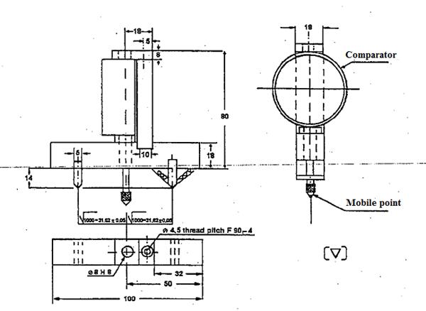
Procedure for determining the radius of curvature “r” of the reflecting surface of a mirror
C.1. MEASUREMENT
C.1.1. Equipment
A “spherometer” similar to the one described in Figure C.1 is used.
C.1.2. Measuring points.
The principal radii of curvature shall be measured at three points situated as close as possible to positions at one-third, one-half and two-thirds of the distance along the arc of the reflecting surface passing through the centre of this surface and parallel to segment b, or of the arc passing through the centre of the reflecting surface which is perpendicular to it if this arc is the longer.
...
...
...
Mọi chi tiết xin liên hệ: ĐT: (028) 3930 3279 DĐ: 0906 22 99 66
“r” expressed in mm is calculated from the formula:
![]()
Where:
rP1: the radius of curvature at the first measuring point (mm).
rP2: the radius of curvature at the second measuring point (mm).
rP3: the radius of curvature at the third measuring point (mm).
Dimensions in mm
...
...
...
Mọi chi tiết xin liên hệ: ĐT: (028) 3930 3279 DĐ: 0906 22 99 66
D.1. Description of the test rig
D.1.1. The test rig consists of a pendulum capable of swinging about two horizontal axes at right angles to each other, one of which is perpendicular to the plane containing the release trajectory of the pendulum. The end of the pendulum comprises a hammer formed by a rigid sphere with a diameter of 165 ± 1 mm having a 5 mm thick rubber covering of Shore A hardness 50.
A device is provided which permits determination of the maximum angle assumed by the arm in the plane of release. A support firmly fixed to the structure of the pendulum serves to hold the specimens in compliance with the impact requirements specified in D.2.5 of this Annex.
Figure D.1 below gives the dimensions of the test rig and the special design specifications:
D.1.2. The centre of percussion of the pendulum coincides with the centre of the sphere, which forms the hammer. It is at a distance 'l' from the axis of oscillation in the release plane, which is equal to 1 m ± 5 mm. The reduced mass of the pendulum is m0 = 6,8 kg ± 0,05 kg.
...
...
...
Mọi chi tiết xin liên hệ: ĐT: (028) 3930 3279 DĐ: 0906 22 99 66

Figure D.1 - Dimensions and special design specifications of the test rig
D.2. Description of the test
D.2.1. Positioning of the mirror or CMS for the test
D.2.1.1. Mirrors or CMS shall be positioned on the pendulum impact rig such that the axes which are horizontal and vertical when the mirror is installed on a vehicle in accordance with the applicant's mounting instructions are in a similar position.
D.2.1.2. When a mirror or CMS is adjustable with respect to the base, the test position shall be that in which any pivoting device is least likely to operate, within the limits of adjustment provided by the applicant.
D.2.1.3. When the mirror or CMS has a device for adjusting its distance from the base, the device must be set in the position in which the distance between the housing and the base is shortest.
D.2.1.4. When the reflecting surface is mobile in the housing, it shall be so adjusted that the upper corner, which is furthest from the vehicle, is in the position of greatest projection relative to the housing.
D.2.2. Except in the case of test 2 for interior mirrors set out in D.2.5.1. of this Annex, when the pendulum is in a vertical position the horizontal and longitudinal vertical planes passing through the centre of the hammer shall pass through the centre of the reflecting surface as defined in paragraph 1.3.12 of this Regulation. The longitudinal direction of oscillation of the pendulum shall be parallel to the longitudinal median plane of the vehicle.
...
...
...
Mọi chi tiết xin liên hệ: ĐT: (028) 3930 3279 DĐ: 0906 22 99 66
D.2.3. When, under the conditions governing adjustment laid down in paragraphs D.2.1.1. and D.2.1.2. parts of the mirror limit the return of the hammer, the point of impact must be displaced in a direction perpendicular to the axis of rotation or pivoting in question. The displacement must be no greater than is strictly necessary for the execution of the test; it must be limited in such a way that:
a) either the sphere delimiting the hammer remains at least tangential to the cylinder as defined in paragraph 2.1.1.5. of this Regulation.
b) or the point of contact with the hammer is located at least 10 mm from the periphery of the reflecting surface.
D.2.4. The test consists in allowing the hammer to fall from a height corresponding to a pendulum angle of 60° from the vertical so that the hammer strikes the mirror at the moment when the pendulum reaches the vertical position.
D.2.5. The mirrors and CMS are subjected to impact under the following different conditions:
D.2.5.1. Mirrors class I
a) Test 1:The points of impact shall be as defined in paragraph D.2.2. of Annex D. The impact must be such that the hammer strikes the mirror on the reflecting surface side.
b) Test 2: Point of impact on the edge of the protective housing, such that the impact produced makes an angle of 45° with the plane of the reflecting surface and is situated in the horizontal plane passing through the centre of that surface. The impact must occur on the reflecting surface side.
D.2.5.2. Mirrors Classes II to VI
...
...
...
Mọi chi tiết xin liên hệ: ĐT: (028) 3930 3279 DĐ: 0906 22 99 66
b) Test 2: The points of impact shall be as defined in paragraphs D.2.2 and D.2.3 of this Annex. The impact must be such that the hammer strikes the mirror on the side opposite to the reflecting surface.
c) Where Class II or III mirrors are fixed to the same mounting as Class IV mirrors, the above mentioned tests shall be executed on the lower mirror. Nevertheless, one or both of these tests on the upper mirror may be repeated if this is less than 2 m from the ground.
D.2.5.3. Camera-Monitor Systems
a) Test 1:The points of impact shall be as defined in paragraphs D.2.2 and D.2.3 of this Annex. The impact shall be such that the hammer strikes the camera on the lens side.
b) Test 2: The points of impact shall be as defined in paragraphs D.2.2 and D.2.3 of this Annex. The impact shall be such that the hammer strikes the camera on the side opposite to the lens.
Where more than one camera is fixed to the same mounting, the abovementioned tests shall be executed on the lower camera. Nevertheless, the Technical Service responsible for testing may repeat one or both of these tests on the upper camera if this is less than 2 m from the ground.
D.2.6. In the tests described in this Annex, the pendulum must continue to swing after impact in such a way that the projection of the position assumed by the arm on the plane of release makes an angle of at least 20° with the vertical.
a) The accuracy of measurement of the angle shall be within ± 1°.
b) This requirement is not applicable to mirrors stuck to the windscreen, in respect of which the requirement stipulated in paragraph 2.4.3 of this Regulation shall apply after the test.
...
...
...
Mọi chi tiết xin liên hệ: ĐT: (028) 3930 3279 DĐ: 0906 22 99 66
Bending test on the protective housing attached to the mirror
E.1. Test apparatus
The test apparatus is described in Figure E.1
E.2. Description of the test
E.2.1. The protective housing is placed horizontally in a device in such a way that it is possible to lock the attachment support adjusters firmly. In the direction of the greatest dimension of the housing, the end nearest to the point of attachment on the adjuster for the support shall be immobilized by a 15 mm-wide rigid stop covering the entire width of the housing.
E.2.2. At the other end, a step identical with the one described above shall be placed on the housing so that the specified test load can be applied to it (see Figure E.1).
E.3. The test loading shall be 25 kilograms and shall be maintained for one minute.
...
...
...
Mọi chi tiết xin liên hệ: ĐT: (028) 3930 3279 DĐ: 0906 22 99 66
Figure E.1 - Example of bending test apparatus for mirror protective housings
- 1 Circular No. 40/2013/TT-BGTVT dated 01st November 2013, on national technical regulations of motor vehicle structure with regard to the prevention of fire risks and on the burning behavior of materials used in the interior structure of certain categories of motor vehicles
- 2 Circular No. 57/2011/TT-BGTVT dated November 17, 2011, on promulgation of three national technical regulations on automotive parts
- 3 Circular No. 57/2011/TT-BGTVT dated November 17, 2011, on promulgation of three national technical regulations on automotive parts
- 1 Circular No. 17/2020/TT-BGDDT dated June 29, 2020 on Regulations on national sign language standards for persons with disabilities
- 2 Circular No. 25/2019/TT-BGTVT dated 05th of July, 2019 on the technical safety and environmental safety inspection in automobile manufature and assembly
- 3 Circular No. 03/2018/TT-BGTVT dated January 10, 2018 technical and environmental safety inspection of imported motor vehicles regulated by Decree 116/2017/ND-CP
- 4 Circular No. 33/2015/TT-BGTVT dated July 24, 2015, introducing the national technical Regulation on 4th – level emissions applying to newly-manufactured, assembled and imported cars
- 5 Circular No. 54/2014/TT-BGTVT dated October 20, 2014, amending Circular No. 31/2011/TT-BGTVT stipulating the inspection of technical safety, quality and environmental protection in manufacturing and assembling motor vehicles
- 6 Circular No. 55/2014/TT- BGTVT dated October 20, 2014, amending Circular No. 31/2011/TT-BGTVT stipulating the inspection of technical safety, quality and environmental protection for imported motor vehicles
- 7 Circular No. 45/2012/TT-BGTVT of October 23, 2012, on the inspection of the technical quality, safety, and environment protection in the p and assembly of motorbikes
- 8 Circular No. 30/2011/TT-BGTVT of April 15, 2011, on the environment protection and technical safety quality inspection in motor vehicle production and assembly
- 9 Circular No. 31/2011/TT-BGTVT of April 15, 2011, regulating the inspection of quality on technical safety and environmental protection for imported motor vehicles
- 10 Decree No. 127/2007/ND-CP of August 01, 2007, detailing the implementation of a number of articles of the Law on Standards and Technical Regulations
- 11 Law No. 68/2006/QH11 of June 29, 2006 on standards and technical regulations
- 1 Circular No. 17/2020/TT-BGDDT dated June 29, 2020 on Regulations on national sign language standards for persons with disabilities
- 2 Circular No. 33/2015/TT-BGTVT dated July 24, 2015, introducing the national technical Regulation on 4th – level emissions applying to newly-manufactured, assembled and imported cars